impeller balancing formula
PDF DYNAMIC BALANCING OF ROTATING MACHINERY EXPERIMENT Technical Advisor ...PDF
This measurement is not needed for balancing the rotor, but will be used later as a check on calculations. 7) Using the equations described in section 6.5 (calculations) determine the 2 masses required at both planes A&B of the rotor to dynamically balance the rotor. These calculations will
Learn More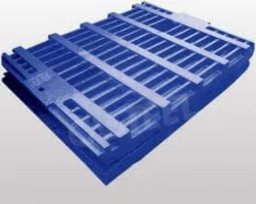
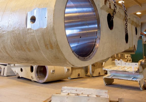
Large Impeller Balancing - Case Study
This is the balancing data from the impeller previously balanced on the arbor. The balance tolerance is applied at the center of the bearing location. As you can see no corrections were needed. 4w/n = 4 (15000) /100 = 600 oz in Second Impeller Assembly The second impeller assembly presented a greater challenge.
Learn More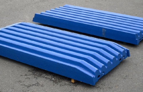
PDF Dynamic BalancingPDF
fact, the force formula (Ref.1, page 1-6) shows that the force caused by unbalance increases by the square of the speed. If the speed is doubled, motor armatures and pump impellers are not. The technique of balancing in place is referred to as Field Balancing and it
Learn More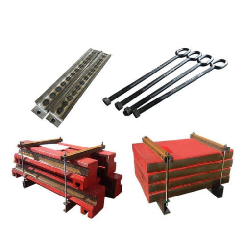
Dynamic Balancing of Centrifugal Pump Impeller - CiteSeerX
The objective of balancing is to reduce rotor vibration to a practical minimum. Reducing rotor vibrations generally increases the service life of the rotating
Learn More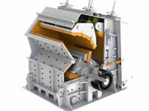
TX303 ABC90 BLADE | impeller balancing formula
TX303 ABC90 BLADE Calaméo. 2 WEAR PROTECTION SOLUTIONS Reliable and efficient solutions throughout the entire material flow For many years, our products have been used as successful problem solvers, we have solved such problems as wear and abrasion, high noise levels and dust propagation, and we have helped reduce heavy maintenance costs, all with the aim of
Learn More
Stability of the axial-auto-balanced impeller of centrifugal pump
2022/9/7 · Based on the Bernoulli’s equation, the formulas of the axial clearance are derived theoretically. The relationship between the impeller axial force, the clearance leakage flow rate and the axial clearance is obtained. The motion differential equation of the axial-auto-balanced impeller is established by the number axis modeling method.
Learn More
PDF Balance Quality Requirements of Rigid Rotors - irdproducts.comPDF
balancing and its terminology if the standard is to be understood and used properly. The reader is directed to the paper's "Balance Terminology" section for a summary of terms used in this paper. USING THE STANDARD The use of the standard involves the following steps: 1. Select a balance quality grade "G number" from Table 1 based on rotor type. 2.
Learn More
Balance Quality Grades for Industrial Centrifugal Fans
To calculate the allowed imbalance for the stricter grade of G2.5 and the most stringent grade of G1.0, we use a simple ratio. We would divide 2.5 by 6.3 or 1 by 6.3 respectively, then multiply the result by the maximum grams of imbalance calculated above. Hear it from an Application Engineer
Learn More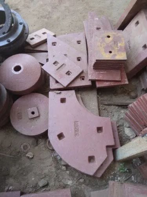
Fundamentals for Successful Field Balancing - Reliabilityweb
To be more precise with actual running speed, the recommended trial weight (Wt) value in ounces is calculated as follows: Wt = 56,375 WR/(N2*r), where rotor
Learn More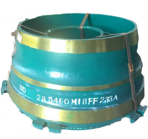
Single Plane Balancing - 3 Point Method
Now, a suitable trial weight has to be attached to the impeller and system response has to be measured at those three points. The trial weight
Learn More
Following Industry Standard Guidelines for Balancing Centrifugal Pumps
For a G1 quality grade, a -20 percent margin is recommended for balancing and a +25 percent is recommended for inspection. In some cases, the manufacturer or repair shop must reconsider whether to continue to balance components to quality grades of G1 or better.
Learn More
Axial thrust - KSB
The axial impeller force (F 1) is the difference between the axial forces on the discharge-side (F d) and suction-side (F s) impeller shroud F 1 = F d – F s Momentum (F J) is a force which constantly acts on the fluid contained in a defined space (see Principle of conservation of momentum, Fluid mechanics ). It is calculated as follows:
Learn More
Chemical Equation Balancer
C 2 H 5 OH + O 2 = CO 2 + H 2 O. This equation is more complex than the previous examples and requires more steps. The most complicated molecule here is C 2 H 5 OH, so balancing begins by placing the coefficient 2 before the CO 2 to balance the carbon atoms. C 2 H 5 OH + O 2 = 2CO 2 + H 2 O.
Learn More
Static and Dynamic Balancing Second Edition
Vibration Meter and Acceierometer. Static Balancing; Measurement and Calculation. Example 1,. To balance a rotor statically by us-.
Learn More
Pump Impeller Dynamic Balancing
Permissible Unbalance (g-mm) = (1000 x balance grade value x weight of impeller in (Kg)/ angular velocity (rad/S) For example, if you have an impeller with 2 Kg weight and with rotor
Learn More
Trial Weight Technical Note - Emerson
AMS 2140 balancing program calculator. Will this be a single or dual plane balance? After gathering the machine's weight of the rotor to be balanced.
Learn More
Single and Dual-plane Rotor Balancing
Single and Dual-plane Rotor Balancing unbalance rotor is stationary, the end masses balance each other. Acceleration to velocity calculation.
Learn More
OMNI937 SUPPORT KEY RETAINER | impeller balancing formula
impeller balancing lt120 final drive spare parts vi400 protection ore mining crusher wear main frame bushing cast iron foundry rw5786hu. impact rock crusher lt1213 parts s&h6800 spare part wearing plate socket liner gold ore crusher cone crusher spare parts. Morris4x4Center. Sitewide Promotions & Free Shipping.
Learn MorePDF Dynamic Balancing of Centrifugal Pump ImpellerPDF
The following formula can be used instead of previous diagram: Et = (9550 / M).G Where, Et [μ] = Total acceptable mass eccentricity 1 Impeller type Single vane impeller 2 Balancing speed 1450 rpm 3 Length of the rotor 210 mm 4 Diameter of the impeller 310 mm 5 Suction diameter 160 mm
Learn More
Impellers Selection Guide: Types, Features, Applications - GlobalSpec
Impellers Information. Impellers (also spelled impellors or impellars ) are rotating devices designed to alter the flow and/or pressure of liquids, gases, and vapors. Impellers consist of various vanes — often blade-shaped — arranged around a short central shaft. When the shaft and vanes rotate, they suck in fluids or gases and impel them
Learn More
Following Industry Standard Guidelines for Balancing
Rotating pump components and impellers are balanced at pump assembly and during production, and should be balanced again when the pump is rebuilt or repaired.
Learn More